How Hall Effect Sensors Work: A Complete Guide for Beginners and Engineers
Hall effect sensors are everywhere. From the brushless motor in your laptop fan to the wheel speed sensors in your car’s ABS system, from contactless switches in smartphones to position detectors in industrial robots — these tiny components are one of the most widely used sensors in modern electronics. Yet for something so ubiquitous, relatively few people understand the elegant physics behind them.
This guide explains exactly how Hall effect sensors work, from the underlying physics to real-world circuit design, giving you everything you need to understand, select, and use them confidently.
The Hall Effect: The Physics Behind the Sensor
To understand how a Hall effect sensor works, you first need to understand the Hall effect itself — a phenomenon discovered by American physicist Edwin Hall in 1879.
Here’s the core idea: when a current-carrying conductor is placed in a magnetic field that is perpendicular to the current flow, a voltage is generated across the conductor — at right angles to both the current and the magnetic field. This voltage is called the Hall voltage.
Let’s break that down with a concrete picture. Imagine a flat, rectangular semiconductor wafer. You pass a current through it from left to right. Now you bring a magnet close, so its field passes through the wafer from top to bottom. The moving electrons (which carry the current) experience a force — called the Lorentz force — that deflects them toward one side of the wafer. As electrons accumulate on one side, that side becomes negatively charged, and the opposite side becomes positively charged. This charge separation creates a measurable voltage across the wafer’s width: the Hall voltage.
The key insight is that the magnitude of this Hall voltage is directly proportional to:
- The strength of the magnetic field (B)
- The current flowing through the material (I)
And inversely proportional to:
- The thickness of the material (d)
- The charge carrier density of the material
The mathematical relationship is: VH = (I × B) / (n × e × d), where n is the charge carrier density and e is the electron charge. For practical sensors, the semiconductor material is chosen to have a low carrier density, which maximises the Hall voltage for a given field, making it easier to detect.
From Raw Physics to a Practical Sensor
The raw Hall voltage produced by the semiconductor element is quite small — typically in the millivolt range. A bare Hall element is not much use on its own. This is where integrated Hall effect sensor ICs come in.
A modern Hall effect sensor IC integrates several components onto a single chip:
- The Hall element — the semiconductor wafer that generates the voltage
- A voltage regulator — to provide a stable supply to the Hall element regardless of variations in the supply voltage
- An amplifier — to amplify the tiny Hall voltage to a usable level
- A Schmitt trigger comparator — to convert the amplified signal to a clean digital output (in digital/switching sensors)
- Output driver circuitry — to drive an external load
This integration means you can power the IC from a 3.3V or 5V supply, bring a magnet close, and get a clean logic-level output in return — without worrying about millivolt-level signals or temperature drift.
Types of Hall Effect Sensors
Hall effect sensors are not all the same. They broadly fall into two categories, each suited to different applications.
1. Switching (Digital) Hall Effect Sensors
These are the most common type. They produce a binary output: either ON or OFF, depending on whether the magnetic field strength exceeds a defined threshold.
Inside the IC, a Schmitt trigger comparator compares the amplified Hall voltage to a reference. When the field exceeds the operate point (BOP), the output switches to active state. It stays active until the field drops below the lower release point (BRP), at which point the output returns to its inactive state. The difference between BOP and BRP is the hysteresis — this prevents noisy or jittery switching near the threshold, which is critical in real-world environments with vibration or electrical noise.
Most digital Hall sensors use an open-drain (or open-collector) output, meaning the output pin can only actively pull low. An external pull-up resistor (typically 1kΩ to 10kΩ) is needed to pull the output high when the sensor is inactive. This open-drain architecture makes these sensors very flexible: the pull-up resistor can be connected to any voltage rail appropriate for your logic, whether that’s 3.3V, 5V, or even higher.
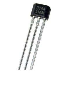
A classic example is the A3144 Hall effect sensor — a widely used unipolar digital switching sensor available in a simple TO-92 package. It activates when a South pole magnetic field of sufficient strength is presented to its branded face, making it ideal for speed sensing, proximity detection, and simple switching applications.
2. Linear (Analogue) Hall Effect Sensors
Linear sensors produce a continuous analogue output voltage that varies proportionally with the magnetic field strength. In the absence of a magnetic field, the output sits at approximately half the supply voltage (the quiescent voltage). A South pole field increases the output above this midpoint; a North pole field decreases it below.
These sensors are ideal for measuring the magnitude and direction of a magnetic field, which makes them suited to applications like current sensing, throttle position measurement, and precise displacement sensing.
Unipolar vs. Bipolar Sensors
Digital Hall effect sensors are further divided by their polarity response:
- Unipolar sensors respond to only one pole of a magnet — typically the South pole. They turn on when the South pole is presented and turn off when it is removed. These are the most common type for general-purpose switching.
- Bipolar sensors require both poles to operate. A South pole turns them on; a North pole turns them off. They are used with ring magnets or back-and-forth actuation where alternate poles pass the sensor.
- Omnipolar sensors respond to either pole of a magnet, turning on when sufficient field is detected regardless of polarity. These simplify magnet orientation requirements in assembly.
Key Specifications to Understand
When selecting a Hall effect sensor, several parameters matter:
- Operate point (BOP): The magnetic flux density (in Gauss or millitesla) at which the output switches to the active state. Lower values mean the sensor is more sensitive.
- Release point (BRP): The field level at which the output returns to inactive. Always lower than BOP due to hysteresis.
- Hysteresis (Bhys): BOP minus BRP. Wider hysteresis means more noise immunity but requires the magnet to move further away before the output resets.
- Supply voltage range (VCC): Most digital sensors operate from 3.5V to 24V, making them compatible with both microcontroller and industrial logic levels.
- Output current (IOUT): How much current the open-drain output can sink. The A3144, for example, can sink up to 25mA continuously.
- Operating temperature range: Hall sensors designed for automotive use typically cover −40°C to +150°C, while standard industrial sensors cover −40°C to +85°C.
- Chopper stabilisation: A technique used in higher-end sensors to cancel out offset voltage caused by mechanical stress on the die, improving accuracy and stability over temperature.
How to Wire a Basic Hall Effect Sensor
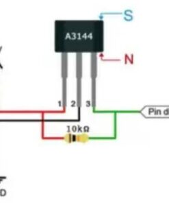
Connecting a three-pin digital Hall effect sensor like the A3144 to a microcontroller is straightforward. The three pins are typically: VCC (power), GND (ground), and Output.
The basic wiring procedure is as follows:
- Connect VCC to your supply voltage (e.g. 5V for an Arduino).
- Connect GND to the common ground of your circuit.
- Connect a pull-up resistor (typically 4.7kΩ to 10kΩ) between the output pin and VCC.
- Connect the output pin to a digital input on your microcontroller.
When no magnet is present, the output is pulled high through the resistor — your microcontroller reads logic HIGH. When a suitable South pole magnet is brought close to the sensor’s branded face, the output transistor turns on and pulls the pin low — your microcontroller reads logic LOW. This active-low behaviour is standard for open-drain Hall sensors.
One important note: many development boards and breakout modules already include a built-in pull-up resistor on the signal line. If you’re using a bare IC like the A3144 on a breadboard, you must add your own.
Magnet Selection and Placement
The Hall sensor is only half of the story — the magnet matters just as much. Here are the key practical points:
- Pole orientation: For unipolar sensors, the South pole must face the branded (front) face of the sensor. Presenting the North pole will have no effect.
- Magnet strength and airgap: The field strength at the sensor face drops rapidly with distance. A small 6mm × 3mm neodymium disc magnet typically actuates a standard Hall sensor at distances up to 10–15mm. Larger magnets or higher-grade neodymium will increase the operating distance.
- Ferromagnetic shielding: If the sensor is mounted near steel or iron, those materials will redirect magnetic flux lines and can significantly alter the operate and release distances. This is a critical design consideration in motors and gearboxes.
- Magnet type: Neodymium (NdFeB) magnets are the strongest per unit volume and are most common in sensor applications. Ferrite magnets are cheaper but weaker. Alnico magnets are used where temperature stability is critical.
Common Applications
Hall effect sensors appear in a remarkably wide range of applications:
- Speed and RPM sensing: A ring of magnets attached to a rotating shaft passes a stationary Hall sensor, generating pulses that can be counted to calculate speed. This principle is used in bicycle computers, motor controllers, washing machines, and automotive wheel speed sensors for ABS.
- Position and proximity detection: Used as contactless limit switches, end-stop sensors on 3D printers, and door/lid detection in appliances and laptops.
- Current sensing: A current-carrying conductor creates a magnetic field. A linear Hall sensor placed near the conductor can measure this field and hence calculate the current — without any electrical connection to the high-voltage circuit. This is invaluable in EV battery management systems and motor drives.
- Brushless motor commutation: Three Hall sensors spaced 120° apart around the stator of a BLDC motor detect rotor position and signal the motor controller when to switch each phase winding.
- Joysticks and throttle controls: Linear Hall sensors measure the position of a magnet attached to a joystick or throttle lever, providing smooth, wear-free position feedback with no potentiometer tracks to degrade over time.
- Anti-tamper and security: Hall sensors can detect when a case is opened (if a magnet is embedded in the lid), triggering alarms or wiping secure data.
Advantages Over Other Sensing Technologies
Hall effect sensors offer a number of compelling advantages that explain their widespread adoption:
- Contactless operation: Because there is no physical contact between sensor and actuator, there is no wear, no arcing, and no bounce — unlike mechanical microswitches.
- Works through non-magnetic materials: Magnetic fields pass freely through plastics, aluminium, and stainless steel, allowing the sensor to be fully sealed inside an enclosure with the magnet on the outside.
- Responds to static fields: Unlike inductive sensors that require a changing magnetic field, Hall sensors can detect a stationary magnet.
- Fast response time: Switching times in the microsecond range make Hall sensors suitable for high-speed applications.
- Wide operating voltage range: Many sensors operate from 3.5V to 24V, simplifying power supply design.
- Low cost: Mass production has made Hall sensor ICs extremely affordable, often costing a few tens of cents in volume.
Limitations to Be Aware Of
No technology is without trade-offs:
- Sensitivity to stray magnetic fields: In environments with strong motors, transformers, or electromagnetic interference, stray fields can cause false triggering. Careful mechanical design and shielding are sometimes required.
- Temperature dependence: The magnetic properties of permanent magnets and the Hall voltage both vary with temperature. High-precision applications may require temperature compensation.
- Fixed sensing axis: A standard Hall sensor only responds to field components perpendicular to the chip face. Tilting the magnet reduces the effective field and can affect operate distances.
- Magnet required: The sensor itself cannot function without an external magnet — this adds a second component to the bill of materials and introduces a potential point of failure if the magnet becomes demagnetised or dislodged.
Choosing the Right Hall Effect Sensor for Your Project
With hundreds of Hall sensors on the market, here’s a practical decision framework:
- Digital or analogue? If you only need to detect presence or absence of a magnet (proximity, speed counting, limit switching), choose a digital switching sensor. If you need to measure position, angle, or field strength continuously, choose a linear sensor.
- Unipolar, bipolar, or omnipolar? For simple proximity with a single magnet, unipolar is usually easiest. For alternating pole ring magnets, use bipolar. For installations where magnet orientation cannot be controlled, choose omnipolar.
- Package: TO-92 packages like the A3144 are easy to use on breadboards and through-hole PCBs. SOT-23 and other SMD packages are better for compact PCB designs. Flat-pack sensors are used where the sensor must be placed flat against a surface.
- Temperature range: Match the sensor’s rated temperature range to your application environment — automotive under-hood applications demand −40°C to +150°C; consumer electronics typically only need 0°C to +70°C.
- Sensitivity: For detecting small or distant magnets, choose a sensor with a low operate point (high sensitivity). For use in high-field environments with many stray fields, a higher operate point may reduce false triggers.
Final Thoughts
Hall effect sensors elegantly translate an invisible physical phenomenon — the interaction between moving charge carriers and a magnetic field — into a reliable, clean electrical signal. Edwin Hall’s 1879 discovery, combined with modern IC integration, has produced one of the most useful and versatile sensing technologies available to engineers and hobbyists alike.
Whether you’re building a brushless motor controller, adding a contactless limit switch to a 3D printer, sensing wheel speed in an electric vehicle, or simply experimenting on a breadboard, understanding the Hall effect gives you the foundation to use these sensors with confidence and to diagnose problems when they arise.
If you’re ready to start experimenting, the A3144 Hall effect sensor is an excellent starting point — affordable, widely available, easy to wire to any microcontroller, and backed by decades of real-world use in everything from consumer electronics to automotive systems.
Sensors