What is ESP32 – A Deep Dive for Beginners
Everything you need to know about Espressif’s flagship SoC — families, variants, development boards, and how to pick the right one for your project.
What the ESP32 actually is
The ESP32 is a system-on-chip (SoC) designed by Espressif Systems, a Shanghai-based semiconductor company. First released in 2016, it succeeded the hugely popular ESP8266 and brought a massive leap in capability: dual-core processing, Bluetooth, more RAM, more GPIO, and a far richer peripheral set — all at a price point under $5 for the bare chip.
The term “ESP32” is commonly used in two ways that beginners often conflate. First, it refers to the original ESP32 chip specifically. Second, it’s used loosely to describe the entire ESP32 product family from Espressif. Context usually makes it clear which is meant, but it’s worth knowing the distinction early.
At its core, the ESP32 is built around an Xtensa LX6 or LX7 processor (depending on the variant), clocked typically at 240 MHz, paired with Wi-Fi and Bluetooth radios on the same die. The integration of wireless connectivity directly into the chip is the key reason it dominates the IoT and hobbyist embedded space — you get a capable microcontroller plus networking in a single, inexpensive package.
The ESP32 chip families
Espressif has released multiple generations and variants under the ESP32 umbrella. Each targets a different set of requirements — from ultra-low power to high-performance compute to audio processing. Here’s a breakdown of the major families:
ESP32 (original)
Dual-core · LX6
- 240 MHz dual-core Xtensa LX6
- 520 KB SRAM
- Wi-Fi 802.11 b/g/n
- Bluetooth 4.2 + BLE
- 34 GPIO, 12-bit ADC, DAC
- Hall sensor, capacitive touch
ESP32-S2
Single-core · USB native
- 240 MHz single-core LX7
- 320 KB SRAM
- Wi-Fi only (no Bluetooth)
- Native USB (USB OTG)
- 43 GPIO, touch sensors
- Lower power than original
ESP32-S3
Dual-core · AI accelerator
- 240 MHz dual-core LX7
- 512 KB SRAM
- Wi-Fi + Bluetooth 5 + BLE
- Native USB (USB OTG)
- Vector instructions for ML
- 45 GPIO, SPI LCD support
ESP32-C3
RISC-V · Ultra-cheap
- 160 MHz single-core RISC-V
- 400 KB SRAM
- Wi-Fi + Bluetooth 5 + BLE
- Native USB (on some variants)
- 22 GPIO
- Lowest BOM cost in family
ESP32-C6
RISC-V · Matter/Thread
- 160 MHz single-core RISC-V
- 512 KB SRAM
- Wi-Fi 6 (802.11ax)
- Bluetooth 5 + Thread/Zigbee
- IEEE 802.15.4 radio
- Target: smart home products
ESP32-H2
RISC-V · 802.15.4 only
- 96 MHz single-core RISC-V
- 320 KB SRAM
- No Wi-Fi
- Bluetooth 5 + Thread/Zigbee
- IEEE 802.15.4 mesh networking
- Ultra-low power mesh nodes
The architectural shift from Xtensa LX6 (original ESP32) to LX7 (S2, S3) and then RISC-V (C3, C6, H2) is notable. The RISC-V variants have a significant long-term advantage: the RISC-V ISA is open, meaning toolchain support across GCC, LLVM, and others is robust and growing. If you’re starting a new product today and don’t need Bluetooth Classic, a RISC-V ESP32 is worth strongly considering.
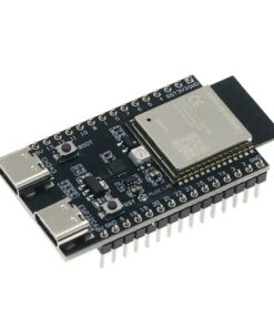
Development boards overview
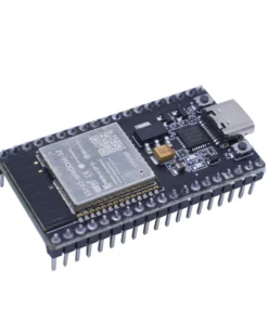
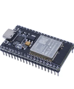
The raw ESP32 chip is a small, surface-mount component you can’t easily plug into a breadboard. Development boards solve this — they mount the chip (often as a module like the ESP32-WROOM or ESP32-WROVER), break out the pins to 2.54mm headers, add a USB-to-serial chip for programming, a voltage regulator, and sometimes extras like buttons, LEDs, or displays.
There are two layers to understand here: modules and dev boards.
Modules (e.g., ESP32-WROOM-32)
A module is the chip plus external flash (and sometimes PSRAM), an antenna (PCB trace or connector), and a metal RF shield, all on a small PCB with castellated edges. Modules are what manufacturers use in finished products — they’re certified (CE, FCC), which saves enormous compliance cost. The most common ones you’ll see are ESP32-WROOM-32, ESP32-WROVER (adds PSRAM), and their S2/S3/C3 equivalents.
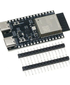
Dev boards (e.g., ESP32 DevKitC, NodeMCU)
A dev board takes a module and adds everything needed to program it from a laptop: a USB connector, CH340/CP2102/FTDI USB-serial chip, reset and boot buttons, and pin headers. This is what most hobbyists buy and use.
Popular dev boards compared
| BOARD | CHIP | KEY FEATURES |
|---|---|---|
| ESP32 DevKitC | ESP32 (original) | 38 pins, WROOM-32 module, wide availability |
| NodeMCU-32S | ESP32 (original) | 38 pins, breadboard-friendly, CP2102 |
| ESP32-WROVER-DevKit | ESP32 (original) | WROVER module with 4MB PSRAM |
| ESP32-CAM | ESP32 (original) | OV2640 camera, SD slot, no USB serial |
| LOLIN D32 | ESP32 (original) | LiPo charging, 4MB flash, compact |
| Adafruit HUZZAH32 | ESP32 (original) | LiPo charging, Feather footprint, polished docs |
| ESP32-S2-DevKitM-1 | ESP32-S2 | Native USB, 32 GPIO, no BT |
| ESP32-S3-DevKitC-1 | ESP32-S3 | Native USB, 45 GPIO, BLE 5, vector ext. |
| Seeed XIAO ESP32-S3 | ESP32-S3 | Tiny (21×17mm), LiPo, camera connector |
| ESP32-C3-DevKitM-1 | ESP32-C3 | RISC-V, native USB, cheapest BOM |
| ESP32-C6-DevKitC-1 | ESP32-C6 | Wi-Fi 6, Thread/Zigbee, Matter-ready |
| M5Stack Core2 | ESP32 (original) | 2″ touch display, IMU, speaker, battery, modular ecosystem |
How to pick the right board
The decision tree isn’t complicated once you know what you’re optimizing for. Here are the major axes:
You need Bluetooth Classic
Original ESP32 only
- Serial SPP, A2DP audio streaming
- Connecting to phones, headsets, classic BT devices
- All newer variants (S2, C3, etc.) dropped it
You need native USB
S2, S3, or C3
- USB HID (keyboard, gamepad, MIDI controller)
- USB CDC serial without a CH340 chip
- Mass storage device emulation
Running TensorFlow Lite
ESP32-S3
- Vector instructions accelerate ML inference
- More SRAM (512 KB) + PSRAM option
- Wake-word detection, image classification
Building a product at scale
C3 or C6
- Cheapest BOM in the family
- RISC-V = excellent open toolchain support
- C6 if Matter/Thread compliance matters
Battery-powered sensor node
ESP32 original or S2
- Deep sleep current as low as 10 µA
- ULP coprocessor for wake-on-sensor patterns
- S2 has lower active current than original
Complete beginner
ESP32 DevKitC or HUZZAH32
- Massive community, endless tutorials
- Arduino IDE support is rock-solid
- Every peripheral library targets this first
Programming and toolchain
There are three main ways to program an ESP32, each with distinct trade-offs:
Arduino IDE / Arduino-ESP32 framework
The most beginner-friendly option. Espressif maintains an official Arduino core that maps the ESP-IDF APIs to the familiar Arduino API surface (setup(), loop(), analogRead(), etc.). You lose some advanced features and the abstractions can hide important behaviors (like how the Wi-Fi stack runs on Core 0 by default), but for most projects it’s entirely adequate.
ESP-IDF (IoT Development Framework)
This is Espressif’s native C/C++ framework and the foundation everything else builds on. It exposes FreeRTOS directly, gives you fine-grained control over both CPU cores, precise power management, and access to every peripheral at the register level. It’s significantly more complex — you write CMake-based projects, manage tasks and queues manually, and configure the system via menuconfig. This is what professional firmware engineers use for production devices. If you’re building a product that ships, learn ESP-IDF.
MicroPython / CircuitPython
Running Python on the ESP32 trades raw performance for development speed. MicroPython has solid ESP32 support and is excellent for scripting, rapid prototyping, or projects where a non-programmer needs to modify behavior. CircuitPython (Adafruit’s fork) is even more beginner-focused and works well on S2 and S3 boards with native USB. The catch: anything time-sensitive, interrupt-heavy, or computationally intensive will hit MicroPython’s limits quickly.
Common pitfalls
GPIO numbering confusion. The pin numbers silkscreened on your dev board are often not GPIO numbers. A pin labeled “D5” on a NodeMCU might be GPIO14. Always cross-reference your board’s pinout diagram, not the physical label. Several GPIO pins are also input-only (GPIO34–39 on the original) — you cannot use them as outputs no matter what.
Strapping pins. GPIO0, GPIO2, GPIO12, and GPIO15 on the original ESP32 are strapping pins — they determine boot mode. Connecting hardware to these pins (buttons, sensors, LEDs) can prevent the chip from booting or entering programming mode. Check the datasheet before using them.
3.3V logic. The ESP32 is a 3.3V device. All GPIO pins are 3.3V logic — they are not 5V tolerant on most variants. Connecting a 5V sensor directly can permanently damage the chip. Use a level shifter or voltage divider.
Current limits. Each GPIO pin can source/sink around 40 mA maximum, but the total current across all GPIO simultaneously is limited. Don’t drive multiple LEDs directly from GPIO without current-limiting resistors, and don’t power motors or relays directly — use transistors or motor driver ICs.
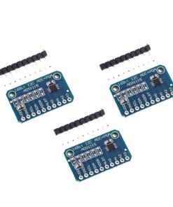
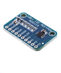
ADC accuracy. The ESP32’s ADC is notoriously noisy and non-linear, especially ADC2 which shares pins with the Wi-Fi radio and becomes unusable while Wi-Fi is active. For precise analog measurements, use an external ADC (ADS1115 over I2C is a popular choice).
Microcontrollers